
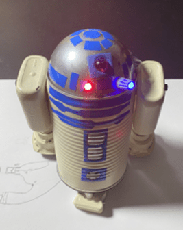
 The is a great project! It gets a little “fiddly” at times but it is one that starts with a box of parts on day one finishes with a complete illuminated model on the second day. It’s also dear to me because the high percentage of reused materials. Note in the picture to the left that the display case is also made of reused materials. A Christmas decoration came in the clear drum. The top is a spare sink stopper hot glued to the top. During my first build day, I cleaned and painted the materials. Vinyl decorations were
 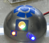 cut out with a razor blade on plexiglass and applied. The arms were assembled from FireBall mini bottles and automotive air fresheners. I also painted the fabric softener dome top.
On the second day, the LEDs and current limiting resistors are mounted followed by mounting the dome on the top of the can with hot glue.
It made most sense to mount the push button on/off switch and the power socket before mounting the battery holder. Unlike the TARDIS, R2D2 is NOT bigger on the inside and it gets crowded quickly.
The 3 AA battery holder is mounted on a ¾” piece of plywood cut to 2″ square and sanded on one side to fit on  the inside of the soup can. A belt sander makes this particularly easy since it can remove a lot of material quickly. I placed sticky hook and loop fasteners (Velcro) to the battery pack and the mounting platform and hot glued the assembly to the front of the robot. I may want to replace the batteries in the future and having the holder mounted on Velcro will allow me to remove the holder when required.
Having a battery operated R2D2 tin can robot is neat. It allows me to put it anywhere on display independent of the need for a wall socket. However, most of my displayed tin can robots are on a shelf and powered by an external power supply. Honestly, I don’t know where this one is going to end up so I added the capability to operate on an external power supply.
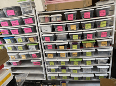 I bought D.C. power sockets and plugs in the past for previous projects, so I knew that they were available—somewhere. After a short search that felt longer than it was, I came up with the socket and plug combination. I also had an Apple USB charger adaptor that someone conveniently left for me on the side of my walking path. Finally, a quick rummage through the “wire box” and I had the needed USB wire. Once again, I had the pleasure of using materials that I had on hand.
This is hard to admit but 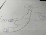 wiring this little robot toy is terribly confusing, and it shouldn’t be. There are only a couple of components and a few connections. Even though this was my fourth one, I had to get out my pencil and paper and turn down the radio so that I could concentrate. I’ll include the diagram here but it’s hard to follow. The secret appears to be that the ground connection is the one that is switched. In my experience, it is usually the positive lead that is switched. In this case, the battery positive lead, the socket positive lead, and the LED positive lead are solidly connected without an interrupting switch. The pushbutton switch on the back of R2 interrupts the ground to the LEDs. One end is connected to the LEDs and other end is connected to the socket negative lead. On my socket there was a connection without a wire, a bare connection. I checked with an Ohmmeter and found that when the plug is not in the socket this bare connection and the ground connection are shorted. Once the plug is inserted, the bare connection and the socket ground connection are disconnected, and the ground provided to the LEDs is from the external power supply.
The allows the robot to operate on batteries when the plug is not in the socket. TA DA!


Pingback: The Robot Marionette | AZAtheist's Blog